Category: Restoration

  • The Great Inkwell Experiment Part Six—Fourth-Week Results

    Inkwell Experiment Results Graph-Final

      1. glass well with a simple gravity-closing hinged lid;
      2. glass well with a silver snap-close hinged lid;
      3. metal well with glass insert and a hinged outer cover (thus with space between the insert and the cover);
      4. wooden well with glass insert and an unhinged cloth-lined wooden lid;
      5. glass writing-box bottle, with threaded brass lid;
      6. pottery ink bottle, with a new, replacement, cork;
      7. (control) plastic graduated cylinder, open;
      8. (control) modern glass ink bottle with plastic lid and synthetic lid liner (J. Herbin).

    The final results are in! (And great thanks goes to Sleepy at FPN for his work on tweaking the chart so that it is more readable.) Full data to date can be seen here.

    We are working on a full version of the experiment results, complete with data, chart, observations, conclusions, discussion, and more. We hope to be done in the next few days, so hurry back…

  • The Great Inkwell Experiment Part Five—Third-Week Results

    Inkwell Experiment Results Graph-Week Three

      1. glass well with a simple gravity-closing hinged lid;
      2. glass well with a silver snap-close hinged lid;
      3. metal well with glass insert and a hinged outer cover (thus with space between the insert and the cover);
      4. wooden well with glass insert and an unhinged cloth-lined wooden lid;
      5. glass writing-box bottle, with threaded brass lid;
      6. pottery ink bottle, with a new, replacement, cork;
      7. (control) plastic graduated cylinder, open;
      8. (control) modern glass ink bottle with plastic lid and synthetic lid liner (J. Herbin).

    Week three results are in! And it seems that I’m finally getting the hang of Excel (or, more specifically, how to make readable charts using Excel.) Full data to date can be seen here.

    As expected, the brass inkwell went dry last Saturday. Interestingly, even the modern, very effective, ink bottle is exhibiting some loss over time.

    And it seems that the time-honoured solutions of using natural products such as cork (the stopper for F) and wood (the case for D) are very effective. It reminds me of the Japanese chests, made of paulonia wood (the same wood as many traditionally-made Japanese kitchen knives). One significant characteristic of paulonia is that it absorbs huge amounts of water, very quickly. The reports are that, when caught in a flood, the drawers of these chests swell shut almost instantly, perfectly preserving the clothing inside them. It made me wonder if the wood of inkwell D is simply swelling shut enough to limit air exchange, and thus evaporation.

    In any case, one more week to go, and then on to conclusions and full data. Tune in next Friday…

  • The Great Inkwell Experiment Part Four—Second-Week Results

    Inkwell Experiment Results Graph-Week Two

      1. glass well with a simple gravity-closing hinged lid;
      2. glass well with a silver snap-close hinged lid;
      3. metal well with glass insert and a hinged outer cover (thus with space between the insert and the cover);
      4. wooden well with glass insert and an unhinged cloth-lined wooden lid;
      5. glass writing-box bottle, with threaded brass lid;
      6. pottery ink bottle, with a new, replacement, cork;
      7. (control) plastic graduated cylinder, open;
      8. (control) modern glass ink bottle with plastic lid and synthetic lid liner (J. Herbin).

    In week two of our experiment the trends continue pretty much as expected. The good are very good, there are a few in the middle of the pack, and the bad are very ugly. And dry.

    It is pretty obvious that C is a complete failure, without some kind of retrofitted seal. Likely it will be completely empty by day fifteen. We have several similar types of inkwell in stock, and we may set up a repeat experiment among similar types, just to see what kind of variables different designs introduce. We are intrigued as to the possible reasons for a covered inkwell to out-under-perform an open cylinder!

    All this being said, we can certainly make lemonade of the lemon-ish inkwells in this experiment. We are already thinking about ways of making tasteful cork stoppers for old inkwells…

    In the mean time, we will continue through the four week period of the experiment, even though the trends are pretty obvious. We shall post the next update in about a week’s time.

  • The Great Inkwell Experiment Part Three—First-Week Results

    Inkwell Experiment Results Graph-Week One

      1. glass well with a simple gravity-closing hinged lid;
      2. glass well with a silver snap-close hinged lid;
      3. metal well with glass insert and a hinged outer cover (thus with space between the insert and the cover);
      4. wooden well with glass insert and an unhinged cloth-lined wooden lid;
      5. glass writing-box bottle, with threaded brass lid;
      6. pottery ink bottle, with a new, replacement, cork;
      7. (control) plastic graduated cylinder, open;
      8. (control) modern glass ink bottle with plastic lid and synthetic lid liner (J. Herbin).

    Here are the results of the first week’s observations. There are some interesting observations, and some obvious conclusions.

    Firstly, there was some up and down fluctuation of mass for the first couple of days. I’m not sure why this was the case, but a longer observation period may shine more light on this.

    Secondly, the pottery ink bottle (with new cork) is among the top performers, with 100% retention.

    Thirdly, and this is the obvious conclusion, even at this early date, the simple glass insert in a metal holder with a fairly loose lid (C) is doing abysmally. In fact, it is doing worse than the open control container. Ironically, this type is among the most available today.

    (As a side note, this puts me in mind of the old axiom about suits of armour in museums: their small size is not because the people in medieval times were physically smaller than we are today. They are smaller because the surviving suits were ornamentally made, largely for the young nobility. The truly representative armour was always used to pieces, literally, on the battlefield; too valuable to store away where it would be preserved for posterity and scholars. Perhaps the really efficient inkwells were used so much that there aren’t many left?)

    Of significant contrast is the fact that the wooden-cased inkwell (D), despite a similar overall design to C, has almost no loss.

    We shall continue with the experiment in the weeks to come; expect the next batch of results a week from today.

  • The Great Inkwell Experiment

    There have been several thoughts expressed to us recently, showing concern about how useful old inkwells actually are, due to evaporation rates. It occurred to us that it might be useful to have some empirical evidence either for or against (or, more likely still, both) this feeling. We have a number of inkwells in our stock, spanning a couple of centuries and any number of designs, so we are in a good position to try out a variety of types. It is our hope that this will provide everyone with a better idea of what to look for—or not—in an inkwell for regular use. (Conversely, we may even prove that inkwells are useless in modern life. Who knows?)

    proposal:
    1. Six inkwells of different design will be filled and closed with nothing more than their original lids. Included will be:

      1. glass well with a simple gravity-closing hinged lid;
      2. glass well with a silver snap-close hinged lid;
      3. metal well with glass insert and a hinged outer cover (thus with space between the insert and the cover);
      4. wooden well with glass insert and an unhinged cloth-lined wooden lid;
      5. glass writing-box bottle, with threaded brass lid;
      6. pottery ink bottle, with a new, replacement, cork;
      7. (control) plastic graduated cylinder, open;
      8. (control) modern glass ink bottle with plastic lid and synthetic lid liner (J. Herbin).
    2. Each container will be filled with distilled water. As we are comparing loss from an inkwell, rather than how different inks evaporate, the actual material won’t make a difference so long as it is consistent through all of the containers. Notably, water has several advantages:

      1. it has universally known qualities: everyone knows how water behaves in their own environment, and it will thus be easier to translate how water behaves relative to your own preferred ink, rather than, say, comparing how the J. Herbin ink in the experiment compares to your Noodler’s;
      2. it is easily available, should anyone want to duplicate this experiment;
      3. it is clean and cheap.
    3. All containers will be kept in the same enclosed space (a section of our lawyer’s bookcase.) Relative humidity will be recorded daily.
    4. Each container will be opened briefly on every seventh day. This will help to approximate the air exchange which happens during normal use. While some people may open their ink containers more often, and some less often, we felt that once-per-week is a good compromise which will reflect average use. When it comes to evaporation, this is actually a fairly important factor. A gas (in this case, the ink solvent represented by water vapour) will expand to fill all available air in a given pressure system. In plain language, fresh air is empty space for the water vapour to fill, and every time you open your ink container, you let in more fresh air. How much of a difference will this make to ink evaporation? I’m not sure, but we are trying to duplicate normal use, and normal use includes letting in fresh air every time you fill or dip your pen. And, we are only opening the containers briefly because the majority of users are filling fountain pens; the variation between dip pen and fountain pen use might be a subject for future study.
    5. Each container will be monitored by weight daily, for four weeks. (Mass is more accurate than volume, as we won’t lose any volume to the testing equipment. And it’s cleaner and easier.) We will use the metric system throughout, as it can accurately place data to multiple decimal places. This is important, as we can trace even the minimal loss of volume from tighter-fitting lids.
    6. Data will be recorded and converted to per cent loss, and the final results graphed. We will post the results on a weekly basis, as it’s more fun that way. Results will be posted to both the Fountain Pen Network and here, in our blog. Additionally, we will publish the results electronically (in PDF format) and encourage wide distribution.
  • Breaking Down a Parker Vacumatic Filler Unit

    One of the giants of American pen manufacturing, Parker, produced millions of pens using the vacumatic filling system. It proved to be reliable, provided for a huge amount of ink storage, but also intimidates many collectors. We hope that this complete tear-down will remove much of the mystique from this venerable but reliable piece of fountain pen hardware.

    To begin with, fountain pens had sacs to hold the ink. Housed in the pen barrel, various methods were used to squish, twist, or press the air out of them, providing suction to draw up a supply of ink. In the 1930s, Parker developed the proprietary vacumatic filling system. Instead of a sac, the barrel itself housed the ink. A rubber diaphragm was installed between the ink chamber and a spring-loaded pump which, when depressed, would force air out of the chamber, creating a mild vacuum which would pull ink into the chamber. For detailed drawings, see Richard Binder’s very excellent Anatomy of a Fountain Pen II: The Parker Vacumatic

    There can be, however, some confusion as to the state of the pieces. Are they glued together? Is shellac involved? Let’s look at a later-1940s filler unit, as this is often the kind encountered.

    1. The Teardown

    Vac-filler Teardown

    This is the complete filler unit, taken from a Parker “51”. It looks pretty complicated, especially compared to simple squish-the-sac filler systems. However, when you reduce it to its component parts, it is not nearly so fearsome.

    Vac-filler Teardown

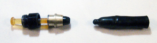
    Our first step is to remove the pellet socket. The plastic used in manufacturing these sockets is, sixty years later, quite brittle. Try this at home and you will likely shatter it (ours happened to be loose on the plunger.) This is the one piece glued on originally.

    Vac-filler Teardown

    The next piece is the retaining collar. Keep in mind that this piece floats freely on the plunger shaft/spring, and should easily come off.

    Vac-filler Teardown

    Vac-filler Teardown

    The spring end is fit between the prongs on the end of the plunger and is not glued, but is instead kept in place by the pellet socket. Over time these prongs can lose their flexibility, causing the pellet socket to become loose; a drop of cyanoacrylate glue will hold it in place.

    Vac-filler Teardown

    Finally, the threaded securing screw slides off the plunger. This can be made of aluminum or, more rarely, plastic. Again, this is a freely floating piece, not attached in any way to the other pieces.

    2. The Spring and Retaining Collar

    Vac-filler Teardown

    As a bit of an aside, let’s look at the relationship between the spring and the retaining collar. The larger-wound end is held in place simply by virtue of it’s large diameter; no glue or shellac need be applied. Occasionally it gets pulled down inside a bit, and may seem to be glued in place. It’s not, and can be gently but firmly worked loose: use a twisting motion, which will take advantage of the coiled shape of the spring to ‘unscrew’ it from it’s seat.

    3. Rebuilding

    Generally cleaning is just a case of giving everything a good soak in warm ammonia water. This will soften any caked-on rubber or other unidentifiable muck, and dissolve any leaked ink. Use an old toothbrush to clean out the crevices, and repeat the process until things are freely moving. A dental scaler is excellent for paring away hardened rubber from around the tapered seat on the retaining collar.

    We cannot overstate the importance of thoroughly cleaning the threads of the securing screw. If any crud remains on the screw itself, in the barrel threads, or in the blind-cap threads, then the pen will likely not go back together properly. At least, the blind cap will sit askew; at worst, the diaphragm seal will be compromised and the barrel will leak. Again, we turn to the dentists: a pick is excellent for chasing threads (be careful if it is plastic!) Another option is to make a thread-chaser from an old securing screw (this trick can be attributed to Ron Zorn. I refer to mine as the “Zorn tool”.)

    Once clean, the rebuild is simple: we assemble the parts in reverse order.

    4. Installing the New Diaphragm

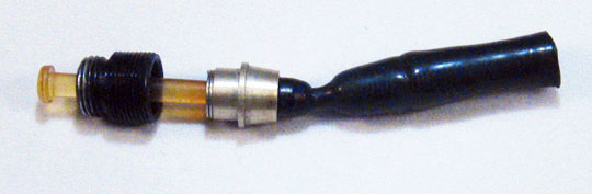
    These filler units take the “debutante”-sized diaphragm. Don’t try to substitute a regular pen sac, however tempting, as it just won’t sit right. Here we have a diaphragm, trimmed to 11/8″ long.

    Vac-filler Teardown

    We seat it firmly in the socket using a tool which will reach up inside the diaphragm to cup the tiny ball inside. A time-honoured tool is the end of a Q-tip which has had the cotton ball trimmed off. Fancier tools can be made of 3/32 brass tubing, but be sure that it is smooth, with no sharp edges, which could damage the rubber.

    Vac-filler Teardown

    Vac-filler Teardown

    We brush the diaphragm with 100% pure talc (and nothing but, please. The last thing you want is gummy cornstarch in the works!) Now the fiddly part: we invert the diaphragm so that it wraps back over itself. It’s stretchy and tough, so just wriggle it back over itself. Occasionally, bad words may ensue. The end should fit snug and flush against the top of the tapered bottom of the retaining collar. If there are any uneven edges, trim them with a sharp blade (you can press right into the collar, it’s tough.) You do not need to secure the diaphragm with any kind of glue or adhesive. The pressure of the securing screw pressing down on the retaining collar will keep it in place.

    Vac-filler Teardown

    Now check that, when you hold the pieces together and fully depress the plunger, the diaphragm is fully extended. If you trimmed it to 11/8″ it should be fine.

    5. Re-installation

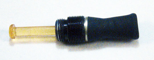
    Re-installation is where all the parts work together: tightening down the securing screw is what holds the mechanism together, rather than glue. The first step is to lubricate the outside of the diaphragm. Don’t skip this step, as rubber is stretchy and grabby; it just won’t work without soapy water, or spit, or K-Y jelly. Take your pick.

    Vac-filler Teardown

    After the rubber is all slippery, gently work the diaphragm down into the barrel. Make sure, during the process, that the end stays seated firmly on the tapered retaining collar. You can easily feel when the works are in place. Using only your fingers, tighten down the threaded securing screw just until it starts to firm up. Now stop.

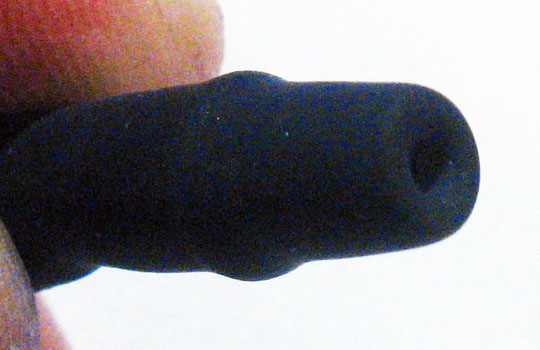
    Reverse the pen, and look down the barrel with a bright light. Push the plunger a few times while you are looking down into the gloom. You should see the end of the diaphragm, damp but completely even, with no creases or folds. It should move smoothly when you push the plunger. If anything looks odd, loosen everything off, pull out the unit, and re-install it. Patience and humility now will save you from stains, frustration, and self-loathing later. If there are any folds or gaps when the diaphragm is tightened down, the pen may leak, fail to fill properly, or even crack when you tighten the securing screw down.

    Vac-filler Teardown

    Once the diaphragm is properly seated, you can tighten down the securing screw properly, using the right tool. (I’m assuming you have one, because you got the unit out in the first place.) Tighten it down so that it is snug, but not too tight. The wide portion of the securing screw should be just below the end of the barrel, like in the photo. If you tighten it too far, the excess pressure could bulge the plastic, or even crack it. Remember, any difficulty you may have had in removing it was likely because of six decades of crud and ossification.

    Vac-filler Teardown

    Try screwing on the blind cap. If it doesn’t feel smooth all around the circumference of the join, try tightening or loosening the unit slightly. If nothing works, take the unit out and re-chase every bit of threading you can find. Then repeat the installation process. A word of warning: should you try to sand down, or otherwise trim the blind cap or barrel to hide the unevenness, the wrath of the Pen Gods will descend, and your remains will be carried away in a small paper bag. Just chase the threads and everything will be alright.

    The vac-filler unit was a brilliant invention, and is still an easily-found part of fountain pen history. A properly serviced vacumatic filler unit will last for decades. We hope this has helped to dis-spell some of the mystique of the process of restoring this simple machine, and will help those trying to preserve those that remain.